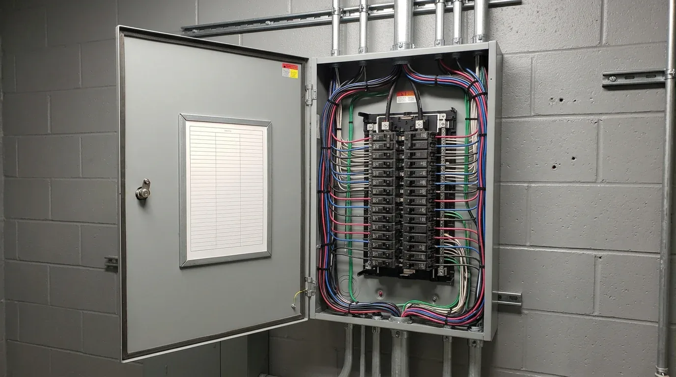
This is a free panel schedule you can fill in on screen or print and fill in by hand. The Excel file has two sheets: single-phase 120/240 V (1Ø, 3W) and three-phase 208Y/120 V (3Ø, 4W). Each has 42 circuits. You type the load in volt-amperes (VA) for every circuit, and formulas add up the VA per phase, the total VA, and the amps per phase. The PDF is the same form, blank, for printing.
What is in the file
- Header block: panel name, location, voltage, main (breaker or main lug only), bus rating, AIC rating, mounting, and what feeds the panel.
- Circuit table: odd circuits on the left, even on the right, the way most panelboards are drawn. Each circuit has a number, a description, poles, breaker amps, and load VA.
- Phase column: a letter for the bus phase each slot sits on. In the single-phase sheet the left side is leg A and the right side is leg B. In the three-phase sheet the rows run A, B, C, A, B, C from top to bottom.
- Load summary: total VA on each phase, amps per phase (VA divided by 120 V), the total VA, the highest phase as a percent of the bus rating, and a count of spare slots.
- Print setup: letter size, landscape, fit to one page wide, with the header text in the footer.
The yellow cells are inputs. Leave the grey cells and the summary alone.
How to fill it in
- Fill the header block. Enter the bus rating as a number (for example 100) so the percent-of-bus line works.
- Write each circuit description the way the drawing does: room or equipment, and what is on it ("Lobby receptacles", "Exhaust fans and restroom lights").
- Enter poles (1, 2 or 3) and breaker amps.
- Enter the load in VA. For a 2-pole or 3-pole breaker, enter each pole's share on the row that pole occupies. A 4,800 VA load on a 2-pole 240 V breaker is 2,400 VA on each of its two slots. That keeps the phase totals right.
- Read the summary. The highest phase tells you how balanced the panel is.
This is a planning aid. It adds what you type. It does not apply demand factors, continuous-load rules or any code calculation. Have a licensed electrician and the current NEC decide those.
How to read a panel schedule on drawings
A panel schedule on a drawing set is the same table, drawn by the engineer. Read it in this order:
- Top block. Find the panel name, voltage and phases, bus rating, main, and AIC rating. The AIC rating is the fault current the equipment is built to interrupt. Compare it with any fault current value shown on the one-line diagram.
- Circuit rows. Each row is a breaker: poles, amps, and a description of what it feeds.
- Load columns. Loads are usually in VA or kVA, split by phase. Some schedules group them by type (lighting, receptacles, motors, other).
- Totals and notes. Look at the connected load, any demand factors the engineer applied, and notes such as "spare", "space" or "future".
Panel schedules often disagree with the plans. A circuit may feed a room that is named differently on the floor plan, or not exist on it at all. Those mismatches are worth an RFI. See our construction RFI template for how to write one.
How estimators cross-check a device count against panel loads
The panel schedule is a free check on a device count. Our method uses it as a standing step when counting a drawing set (see electrical takeoff software). It works like this:
- Pick a circuit on the schedule, for example a lighting circuit.
- Count the devices drawn with that circuit number on the plan.
- Multiply by the per-device load. Fixture VA comes from the luminaire schedule. Receptacles are commonly scheduled at 180 VA each, but use the value the engineer's schedule uses.
- Compare the product with the VA written on the panel schedule row.
If they match, the count is probably right. If they do not, one of three things is true: you missed or double-counted devices, the schedule is rounded or out of date, or the drawing has an error. All three are worth knowing before you bid.
In our own tests this check confirmed the count on a small park restroom sheet, and on a larger office set the gaps went on the list of open questions. The worked example, with the numbers, is in how to read electrical blueprints; the full results are on the sample takeoffs page. The check does not prove a count is perfect. A wrong count can still match if two errors cancel out, and some devices are not on a circuit at all.
Circuits with no matching devices on the plan, and devices with no circuit number, are the most useful finds. A "spare" or "future" row should have no devices drawn.
When to use which sheet
Use the single-phase sheet for residential panels and small commercial panels fed at 120/240 V. Use the three-phase sheet for commercial and industrial panels fed at 208Y/120 V, which is common in offices, schools and retail. If your panel is 480Y/277 V, change the amps formula: the file divides by 120 V, so replace that number with 277 in the summary cells.
Related
Pair this with the electrical estimate template and the voltage drop calculator. For the rest of the sheet, see how to read electrical blueprints.
FAQ
The template is a working form for estimating and planning. Panel schedules on permit drawings are prepared and stamped by the engineer of record. Use this file for takeoff checks and tracking, not as a code-compliance document.
On a 208Y/120 V or 120/240 V system, loads are measured per leg at 120 V to ground, so VA on a phase divided by 120 gives a quick amp figure per phase. It is a simple screening number, not a full load calculation.
No. It adds connected load as you enter it. Demand factors and continuous-load rules come from the NEC and your engineer. Verify with a licensed electrician and the current NEC.
References
Sources
- No outside standard is quoted on this page. For circuit directories, demand factors and continuous loads, use the edition of the NEC (NFPA 70) your jurisdiction has adopted.
No electrician has reviewed this template yet. The 120 V divisor, the circuit layout and the phase rotation follow common practice, so check them against your panel manufacturer's layout.